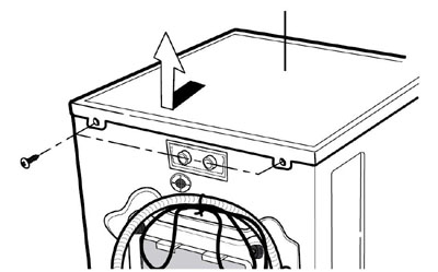
Remove the screws securing the top plate (cover.)
Push the top plate (cover) backward a couple of inches and then lift it off the machine.
The following screens will show the instructions for disassembly, repair, replacement of parts, and re-assembly. Many times, electrical components may be tested by connecting the meter to the appropriate leads or connectors on the main PC Board. (Refer to the wiring diagram for your particular machine. The main menu has one loaded as an example only.)
Proper diagnosis will eliminate unnecessary work and expedite repairs.
Questions? Comments! Concerns? Report an error?
Let us know!
An e-mail should solve the problem.
 |
Remove the screws securing the top plate (cover.) Push the top plate (cover) backward a couple of inches and then lift it off the machine. |
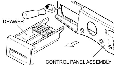 |
Disconnect the cables connecting the washer and the display board. Remove the dispenser drawer by pressing the release tab and pulling it all the way out. Remove the two screws at the dispenser. |
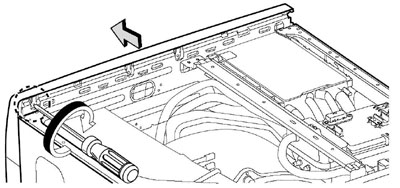 |
Remove the screw from the back of the control panel on the side opposite the dispenser. Lift the top of the control panel and roll it forward slightly to remove it from the machine. |
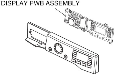 |
Remove the eight screws that secure the display board to the control panel. |
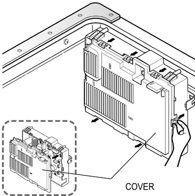 |
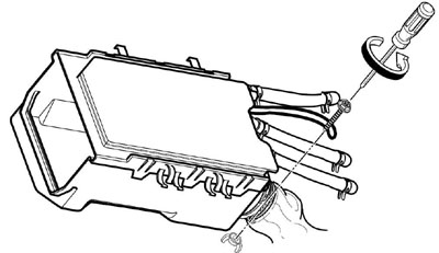
Unplug the machine. Remove the top plate (cover.) Remove the protective cover by prying the plastic clips open. |
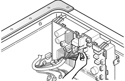 |
Disconnect all electrical connectors. Note that all the connectors are different in pin count, color, and configuration. This makes miswiring virtually impossible. The connectors are labeled on the wiring diagram to show where to make test readings and to make diagnosis easier. Pay attention to pin numbers and wire colors while looking at the schematic. |
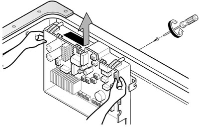 |
To replace the main board, remove the screw that secures it to the back of the machine and slide the board to the right to release it from its brackets. |
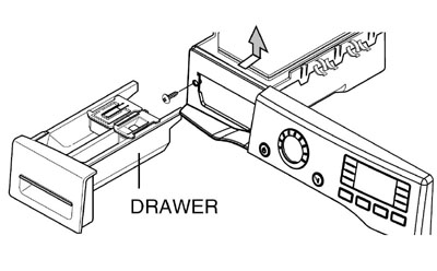 |
Remove the top plate (cover.) Remove the dispenser drawer. Remove the two screws that secure the dispenser body. |
 |
Remove the 5 hose clamps. If you squeeze them and slide them a couple of inches down the hose, they will not be lost while the repair is made. Reconnection will be more convenient if you mark the hoses now. See TEST MODE for information concerning verifying which hose is which. Remove the clamp on the large hose attached to the dispenser. (When you replace it, set it with the screw on top and the wing nut on the bottom for easier reach in the future.) |
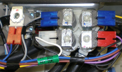 |
Unplug all the solenoids. (As with the hoses, reconnection will be more convenient if you mark
the connectors and valves now.)
Remove the two screws at the back of the machine and lift out the solenoid array. # CONN WIRE COLORS 1 Blue (Yellow and Black) 2 Red (Violet and Black) 3 White (White and Black) 4 Blue (Gray and Black) 5 Red (Blue and Black) (Hot) |
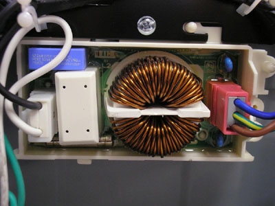 |
To service the noise filter, remove the control panel cover. Unplug the connectors of the noise filter and slide it out of the clips on the frame. NOTICE THAT LINE AND NEUTRAL ARE REVERSED. SEE WIRING DIAGRAM. See the test procedure here. |
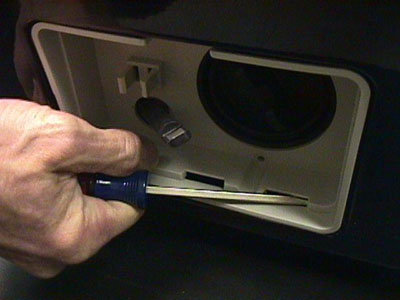 |
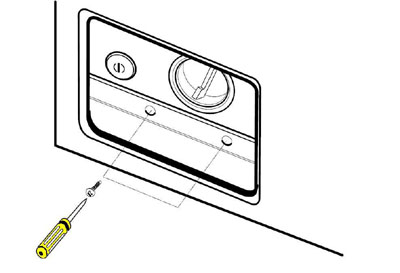
Remove the control panel and top cover and set them aside. Open the filter and drain cover. Remove the screw securing the cover and pry the cover out with a screwdriver or putty knife. Be careful to avoid damaging the rim of the opening. |
 |
With the filter cover removed, remove the screw(s) that secure the base of the front cover to the machine frame. NOTE: On older machines, these are usually rusted and difficult to remove. Some servicers tend to leave out when re-assembling the machine. If the screws are missing, the machine front will probably rattle. |
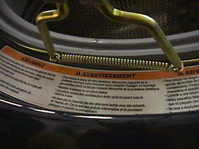 |
Remove the door gasket using special tool 383EER4001A to remove the outer spring clamp. (Click SPECIAL TOOLS on the main WASHER menu.) |
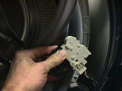 |
After removing the door gasket, you can reach inside the cabinet and unplug the electrical connector to the door switch. If you are replacing the door switch, you can do it without any disassembly other than the door gasket. Remove the two screws that hold the switch in place, pull it out through the opening, and replace it. |
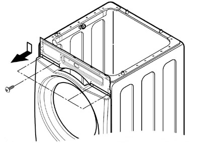 |
Remove the screws that secure the top of the front cover. Be careful that the front does not fall forward, causing injury or damage. (The number of screws may vary, depending upon the model number and whether the machine has been serviced before.) |
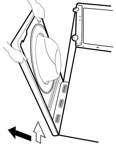 |
Lift the front cover off the tabs at the bottom of the machine. Set it aside face down on a blanket or protective surface. CAUTION! The door is very heavy because of the large glass window. |
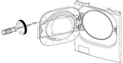 |
Open the door. Remove the screws that secure the hinge cover. The number may vary depending upon the model and the type hinge. Note that washer doors cannot be reversed like dryer doors. |
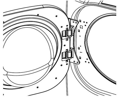 |
Pry the cover off with a screwdriver, taking care not to scratch or mar the surfaces. |
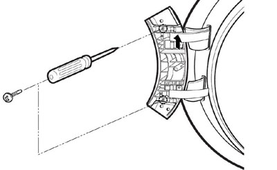 |
Remove the screws from the door hinge clips. Lift the door off the hinge and set it aside. Be sure to retain the plastic hinge shims. |
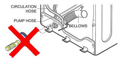 |
Remove the front cabinet. Drain the water from the sump. Remove the clamps and hoses. Since the pump sits on a platform assembly, no screws are used to attach it to the front of the machine frame. |
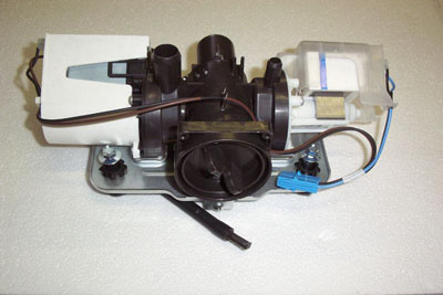 |
Both the drain pump (left) and the circulation pump (right) are mounted on the filter housing. The entire pump assembly is then mounted on a suspension plate base attached to the washer base by three antivibration bushings and 10 mm bolts. Use a socket and a short extension to remove the pump assembly. In older machines, the pump housing slides into a slot on the base of the machine and two screws secure it to the front of the machine base. To release the housing, you'll have to reach behind it blind and press the release tab. The small hose is to allow draining the sump before servicing the washer. |
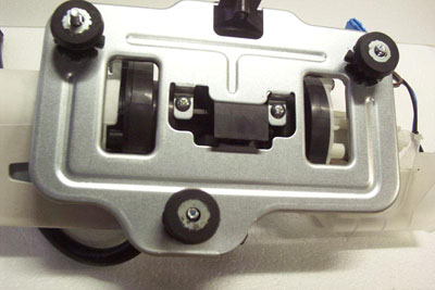 |
Bottom view of the pump and filter assembly, showing the antivibration bushings and bolts and the two screws that hold the pump assembly to the base. Removing the three large bolts allows the entire assembly to be tilted so either pump can be serviced without further disassembly. |
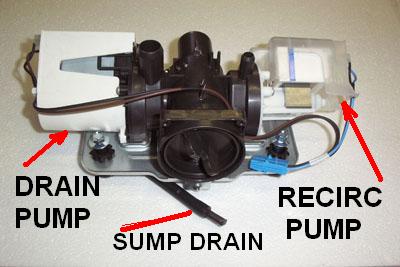 |
Pumps labeled. |
The drain pump and the circulating pump are attached to either side of the filter housing. The drain pump is used to remove the water from the washer. The recirculating pump serves three purposes: it sprays water from the tub onto the laundry to create a better saturation of detergent and better rinsing, it keeps the window clean, and it allows the customer to see water in the tub.
These pumps may fit physically, but they should not be used interchangeably because the flow rates differ.
The filter between the pumps is not a lint filter in the traditional sense. It serves to trap larger objects (keys, coins, buttons, etc.) that may find their way into the washer and protects the pumps from physical damage.
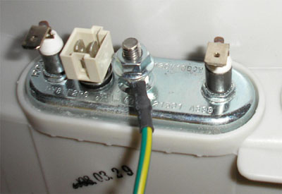 |
Remove the front cover. Disconnect the two electrical connections to the heater leads. Disconnect the thermistor (white plastic connector.) Remove the outer nut and ground wire on the heating element. |
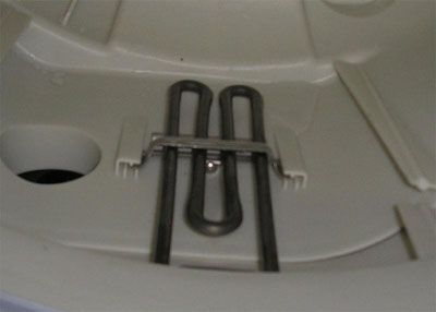 |
Loosen it as far as possible but do not remove the second nut on the ground lug. This will release the tension on the gasket and allow the heater to be pulled out of the tub. When replacing the heater, be sure the element slides into the retaining clip on the bottom of the tub. The round object on the right is the ECO. This is the sensor that determines water hardness and detergent concentration. NOTE! Older models had a thermistor that was not a part of the heater assembly. The thermistor mounted in the hole occupied by the ECO sensor on newer models. If replacing a heater assembly with one that has the thermistor included, the wiring harness will not reach. The official repair method is to replace the wiring harness when replacing the heater with the newer style. Most people will use a couple of short pieces of wire, crimp connectors, and heat shrink tubing to effect the repair. The thermistor is not polarity sensitive, so it doesn't matter which wire connects to which terminal on the thermistor. LEAVE THE ORIGINAL THERMISTOR IN THE RUBBER GROMMET! It will keep water from leaking there. It is now disconnected and will not affect the operation of the machine. |
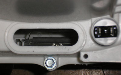 |
Remove the front cover. Remove the heater element, as described above. You can then use a wire to fish out any foreign objects that have come between the drum and the tub. Replace the heater, as described above. |
The water level detector switch monitors the water level and feeds this information to the main board. The sensor reads air pressure in an air chamber on the tub. The air pressure changes in relation to the depth of the water, moving a diaphragm in the switch. As the water level fluctuates, it raises or lowers the iron center in the coil, which, in turn, changes the electric resonance of the oscillator circuit of which it is a part. As water level decreases, frequency increases. (e.g. A low water level may read 25.5 kHz, while a high water level may read 21.4 kHz. These readings are approximate; washers in the field may vary slightly from these figures.) To read the frequency while the WM2801H*A is running, simultaneously press and hold the SOIL LEVEL and WASH / RINSE buttons. The number on the display should be divided by 10 to obtain the frequency reading in kHz. A display of 254 would indicate a frequency of 25.4 kHz. The MICOM interprets the frequency reading as one of eight levels, with one being the lowest water level and any level greater than eight indicating an overflow situation.

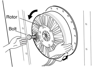 |
Remove the back cover. Remove the large bolt in the center shaft. DO NOT stick a screwdriver or other object through the slots in the rotor. Use a rubber strap to hold the rotor or have a helper hold the drum. Pull the rotor off the shaft. |
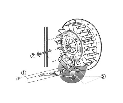 |
Remove the ground screws and wire retainers from the stator wires. The wires need to be free to remove the stator so you can fold it down and unplug the connectors. Remove two screws from the tub bracket. Remove six bolts on the stator. Lift it off and support it while you unplug two connectors on the stator. Set the stator aside. |
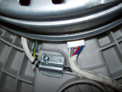 |
When re-installing the stator, the clamps and the ground screw must be installed and the connectors pressed into place before the rotor is bolted onto the shaft. When you replace the rotor, the shaft can be pressed forward so far the bolt will not reach it. If you canít hold the tub back while you install the bolt, get a longer bolt with the same thread. Place the rotor onto the shaft, install the long bolt, and pull the shaft back while you push the rotor all the way on. Then remove the long bolt and replace it with the correct bolt. Tighten to specification. |
|
Removing the tub / drum assembly is major surgery. It is much lighter if you remove the weights and the motor. Generally speaking, youíll have to remove all that anyway. Remove the motor. Drain the water from the sump. Remove the control panel. Remove the front cabinet. Disconnect all hoses and electrical connections. |
 |
Remove the three dampers. You can remove just one pin now and the other end after the drum is out of the machine. Notice that all previous versions of the dampers have been replaced by the newer, double-acting damper. Pry apart the spring retainer clip. Carefully lift the tub up off the springs and remove it from the machine. |
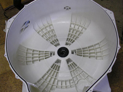 |
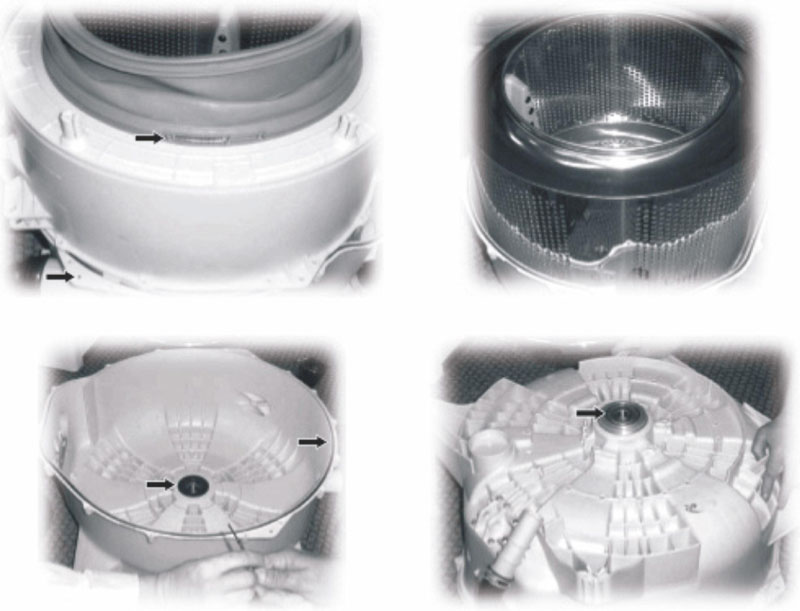
Unbolt the bolts around the circumference of the seam. (top photo) Separate the halves. Be careful to avoid damaging the gasket. Do not pry on the surfaces between the halves. Instead of replacing the bearings, LG recommends purchasing the back half of the tub with the bearings already pressed in at the factory. This definitely NOT a job to attempt in the customer's laundry room. Notice the ribbing on the inside of the tub. These pockets can become gunked up by overuse of detergents, softeners, and other laundry additives. The only way to remove such a build-up is to disassemble the tub halves and clean it manually. It is much better to use |
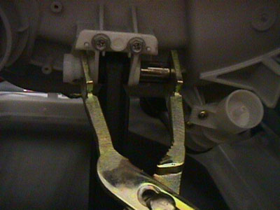 |
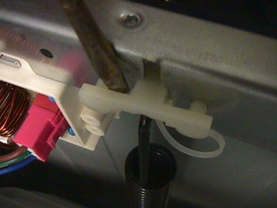
Disconnect the dampers from the tub and the base. Be sure to press in the safety tab before pushing the pin out of the damper. You can use a socket to hold the tab in while you squeeze the pin with the special tool 383EER4003A. (Click SPECIAL TOOLS.) |
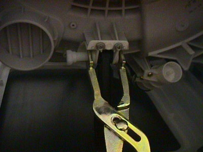 |
The flat end of the tool goes on the small end and the split end allows the head end to pass through while the pin is pushed out. Use a socket to hold the pin down while you press the pin out. The color and/or appearance of the damper may vary by model but the operation is the same. |
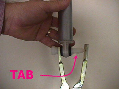 |
Use special tool 383EER4003A to remove the damper pins. (Click SPECIAL TOOLS on the main WASHER menu.)If you are replacing the dampers, youíll have to remove both ends. If you are removing the tub for major repair work, disconnect the damper ends at the base and leave the other ends connected until you remove the tub. When putting the tub back into the machine, connect the dampers to the tub first. It is much easier that way. Be careful not to pull the dampers apart while they are disconnected. If you break them, they must be replaced, and they should be replaced as a set. Notice that ALL previous versions of the dampers have been replaced by the newer, double-acting dampers. |
Questions? Comments! Concerns? Report an error?
Let us know!
An e-mail should solve the problem.