Component Test
Online Training Manual for LG Products - Component Test
COMPONENT TEST PROCEDURES
Several components of the machine can be tested before removing or exchanging them. Some test procedures can be completed without major disassembly other than to disconnect the component from its circuit; others may be tested from their connector on the control panel. Often, the only equipment necessary is a multimeter.
Select a component from the menu or scroll down to find the test procedure.
NOISE FILTER
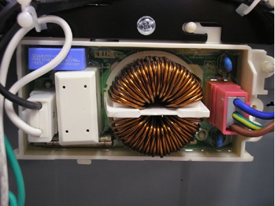 |
The noise filter is designed to keep DC noise from the motor from finding its way back into the house wiring and affecting other appliances, particularly cordless phones, radios, and televisions.
Older models have the wire coil exposed, as shown in the photo.
|
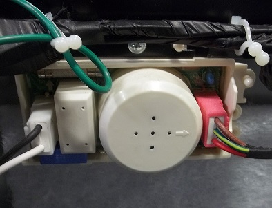 |
More recent models include a plastic cover over the coil for additional safety.
Order part by model number and serial number.
|

Using an ohmmeter, check from the white connector terminal 1 (white wire) to the red connector terminal 1 (blue wire.) The resistance should be 0 ohms.
Then check from the white connector terminal 3 (black wire) to the red connector terminal 3 (brown wire.) The resistance should be 0 ohms.
If these tests pass, reconnect the white connector but not the red connector.
BE AWARE that on some models, the noise filter terminals are crossed; that is, #1 input goes to #3 output, and vice versa. The test procedure is basically the same.
Plug in the machine in. Read the voltage across terminals 1 and 3 of the red (output) connector. It should be approximately 120 VAC, the same as at the outlet.
Back to the list
DOOR LOCK SWITCH ASSEMBLY
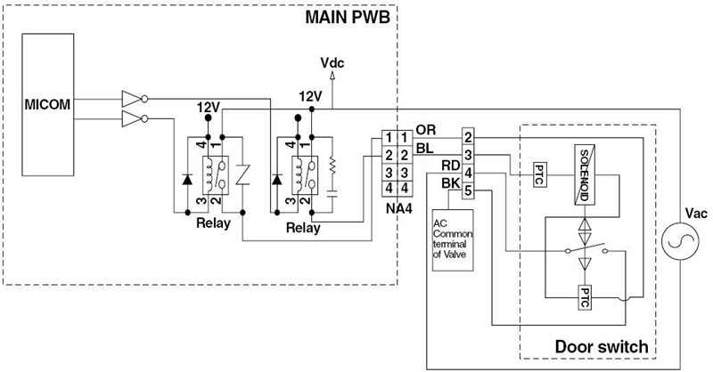
The door lock switch assembly includes a heating PTC, a bimetal, a protection PTC, and a solenoid. The assembly locks the door during the wash cycle and under certain other conditions, such as high temperatures.
DOOR LOCKING
When the system is energized through terminals 2 and 4, the PTCs begin heating. Before the solenoid operation is activated, the cam forces the system to the OFF position. One impulse through terminals 3 and 4 locks the door. The lock is detected by the main board when terminals 4 and 5 are closed.
DOOR UNLOCKING
When the machine is paused, the main board sends an impulse to terminals 3 and 4 and rotates the cam to the open position. The maximum number of impulses is 3. Upon the 4th impulse, the cam reverts to the locked position.
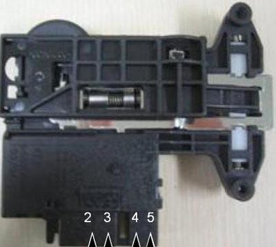 |
Test results at 77° F (25° C)
2 to 3 700 ~ 1,500 ohms
3 to 4 60 ~ 90 ohms
4 to 5 (infinity)
2 to 4 120 VAC (input voltage)
|
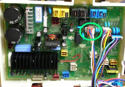 |
At the connector on the main board, the wires are:
OR ORANGE Door Switch (N)
BL BLUE Door Switch (L1)
WH WHITE Main Cold (N)
|
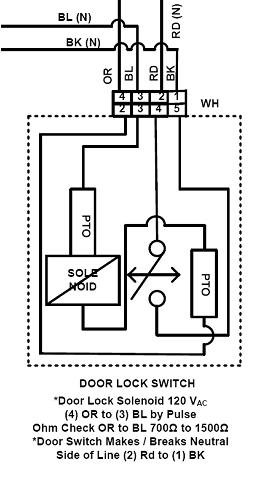 |
The door switch solenoid operates by a pulse of 120 VAC between pins 3 and 4.
With the switch out of the circuit, read the resistance between pins 3 and 4 (ORANGE and BLUE,) which should be 1,100 ohms ± 400 .
The door switch makes or breaks NEUTRAL between pins 1 and 2 (RED and BLACK.)
|
Back to the list
STATOR ASSEMBLY
BE SURE to unplug the machine before making these tests! The motor runs on approximately 310 VDC and a shock could be lethal.
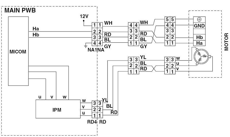
The direct drive brushless DC motor can be driven from zero to the maximum RPM in infinite steps in either direction. There are 36 poles on the stator and 12 permanent magnets on the inside of the rotor. A cracked magnet will cause the motor to stall, generating an LE or Lock Error code on the display.
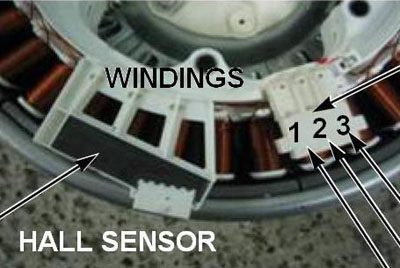 |
The stator can be tested either from its connector, the mid-way connector (in the lower left part of the machine as you face the back of it), or from the connector at the main board. Disconnect before reading the resistance with an ohmmeter.
All test points should read approximately the same resistance. 15, 15, and 14 would be good. 14, 15, and 1 would indicate a failed coil in the stator
1 to 2 5 ~ 15 ohms
2 to 3 5 ~ 15 ohms
1 to 3 5 ~ 15 ohms
|
Back to the list
INLET VALVE ASSEMBLY
The valve assemblies allow water into the tub and release the various laundry products in the dispenser. Hot water enters only through the main wash compartment. Cold water is directed by the remaining solenoids to dispense the various laundry products. Water release may vary, depending upon the machine and the piping.
(See the dispenser section.)
(This diagram and valve array is used as an example only.)
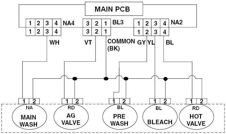
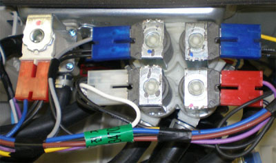
The solenoids can be checked in TEST MODE. Use a multimeter to verify that each solenoid is receiving 120 VAC during the TEST MODE. Also verify that the proper valve is dispensing water to the appropriate dispenser compartment. This procedure can also be used to determine that the valves are connected correctly and the hoses are routed to the appropriate compartments after a repair is complete.
 |
For all solenoids:
With the solenoid connected and energized, the voltage should be 120 VAC.
With the connector removed from the solenoid, the resistance should be 1.0 ohms ± 20%.
|
Back to the list
HEATER DRIVER CIRCUIT
The heater driver circuits are similar for both heaters on the machine: the wash heater, which heats the water in the tub to the specified temperature; and the steam generator heater, which boils water to make steam for the steam cycles. The elements are similar, but not interchangeable, approximately 1,000-watt electric heaters.
The heaters may vary depending upon the series of the machine and the kind of steam system it uses. Steam machines use the separate module of a steam generator. TRU-Steam™ machines use the wash water heater in the base of the tub to heat the water to produce steam.
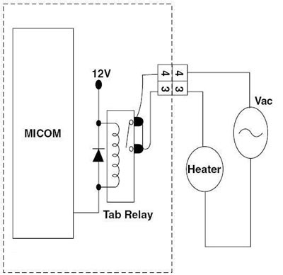 |
When the heater is energized, use your multimeter to read the voltage. It should be approximately 120 VAC.
You can read the voltage either at the heater terminals or at its connector on the main board.
With the heater element disconnected from the circuit, the resistance should be 15 ohms ± 20%.
You can determine if the heater is getting power in the TEST MODE by commecting your meter to the heater leads before running the test. The heater is powered for approximately 3 seconds, so you have to plan ahead and look quickly. Another valid method is to connect your machine through a Kill-A-Watt meter to see is the heater pulls current when activated. If the board supplies power but the heater element is defective, you will not see the current draw during the test.
|
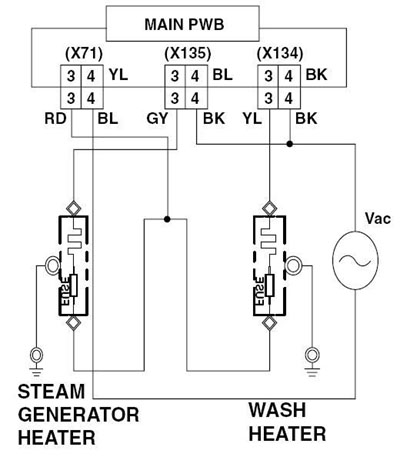 |
When using the connectors for test points, pay particular attention to connector and wire colors and numbers.
|
Back to the list
WASH HEATER
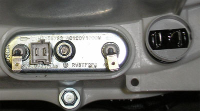 |
The wash heater is at the bottom of the tub where it heats the water in the sump.
Check the voltage to the wash heater by putting your voltmeter on the heater terminals and measuring the voltage, which should be approximately 120 VAC when operating. This voltage can also be measured at the heater’s connector on the main board. There is a point in TEST MODE that activates the dryer heater for 1.5 seconds, so have the meter connected before pressing the test button.
With the heater disconnected from the circuit, it should read 15 ohms ± 20%.
|
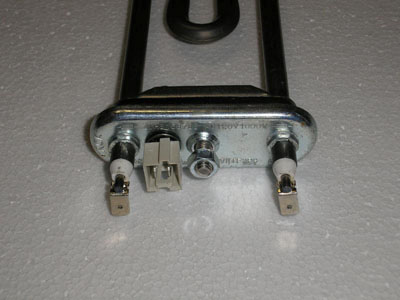 |
To remove the heater, first drain the sump.
Disconnect the electric terminals. Remove the outer nut that holds the ground wire to the center post. Unscrew the second nut on the ground post all the way to the end but do not remove it. This will remove the tension on the gasket and allow the heater to be pulled out.
If a foreign object becomes caught between the drum and tub, it can sometimes be removed through the heater opening using a hooked wire after removing the heater.
|
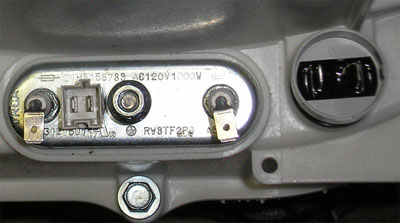 |
The wash heater thermistor can be tested at its connector or at the connector on the main board. Its rubber gasket is a pressure fit in the hole next to the heater. See the section on thermistors.
The round object on the right is the ECO. This is the sensor that determines water hardness and detergent concentration.
NOTE! Older models had a thermistor that was not a part of the heater assembly. The thermistor mounted in the hole occupied by the ECO sensor on newer models. If replacing a heater assembly with one that has the thermistor included, the wiring harness will not reach. The official repair method is to replace the wiring harness when replacing the heater with the newer style. Most people will use a couple of short pieces of wire, crimp connectors, and heat shrink tubing to effect the repair. The thermistor is not polarity sensitive, so it doesn't matter which wire connects to which terminal on the thermistor.
LEAVE THE ORIGINAL THERMISTOR IN THE RUBBER GROMMET!
It will keep water from leaking there. It is now disconnected and will not affect the operation of the machine.
|
Back to the list
STEAM GENERATOR HEATER
The TSG (Turbo Steam Generator) is supplied as an assembly only; parts like the sensors, thermistor, or heater cannot be replaced individually. Diagnosis is limited to determining a malfunction and replacing the assembly. The steam generator does not have to be removed from the machine to be drained. Be sure to let the water cool to avoid a burn. Have a hose available to slip onto the connector and a large towel to catch the water so it doesn’t run down into the machine cabinet. If you remove the steam generator before draining it, be sure to avoid tipping it and spilling the water.
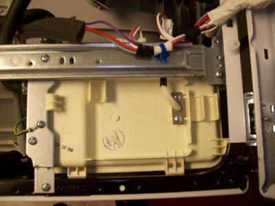 |
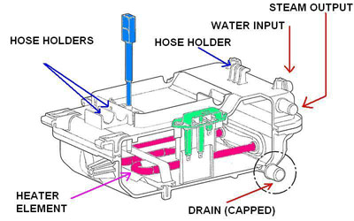
The steam generator has two water connections: water IN and steam OUT. The water is supplied by one of the solenoids on the cold water input valve array. The steam from the generator is directed through a rubber hose to a nozzle at the top of the door gasket, where it sprays out through the laundry as it tumbles.
The electrical connections include 120 VAC to power the heater, ground, water level, and temperature sensors.
|
The electrical components can be tested with the generator in the machine. Unplug the heater and check the resistance across the leads. It should be 15 ohms ± 20%. It can also be checked at its connector on the main board. The voltage can be checked either at the terminals of the heater or at its connector on the main board. There is a test in the TEST MODE that supplies power to the heater briefly. Have your meter connected before pushing the button. (Or connect the machine through a Kill-A-Watt or similar meter.) Water level sensor testing is detailed in the next section, below.
 |
The steam generator can be removed as an assembly for diagnosis and replacement or tested in place.
Unplug the washer.
Disconnect all electrical connections, including ground.
Drain the water. (You can drain the water after removal from the washer and it is easier.) Be careful in case the water in it is still very hot.
|
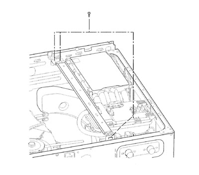 |
Remove all the cable straps by squeezing the tabs and pulling them out. They can be reused.
Remove the four screws holding the support rail in place and two screws attaching the steam generator.
Disconnect the hoses (water input and steam output.) See the next page for a warning concerning the check valve built into the input hose.
|
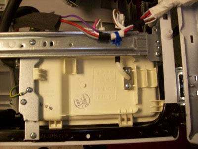 |
Push the steam generator toward the back of the washer to release it from the side rail. You can then remove it for draining, inspection, and replacement.
It is available as an assembly only and is not repairable.
|
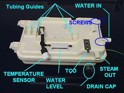 |
When the Turbo Steam Generator is installed in the washer, the hoses to the dispenser should fit into the tubing guides.
|
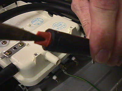 |
Be especially cautious when removing and replacing the water input hose to the steam generator. There is a check valve that fits into the input port. The valve usually comes off and remains stuck in the hose. This could cause the water not to flow, which would cause the steam generator to fail.
|
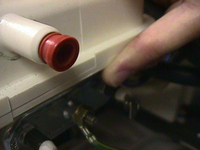 |
Pull the check valve out of the hose gently and replace it into the water input port. Then slide the hose onto the port and install the clamp.
|
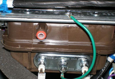 |
Newer models have a retainer built into the check valve to eliminate this issue.
|
Back to the list
WATER LEVEL SENSORS
The Steam Generator is made up of 5 major components. They are the 1,100 watt heater @ 120 VAC, the low water sensor, the high water sensor, the temperature sensing thermistor, and the water tank.
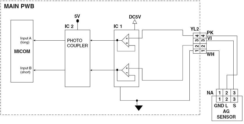
The water level sensors, the thermistor, along with the control board determine IF the steam generator heater will be activated. To the left and above you will see the wiring diagram for the water level sensors. The picture above shows 3 connectors. The rear connector with black and white leads is the temperature sensing thermistor. The center connector with a pink and white wire is the low water sensor. The front connector with a single violet lead is the high water sensor.
From the wiring diagram you will see that the WHITE wire (NA) is the GROUND reference. The PINK wire is the low water sensor lead. The VIOLET lead is the high water sensor lead.
Low Water Sensor Detecting Water
 |
The sensors operate in a 5 VDC environment. When water is present and conductivity exists from the WHITE GROUND lead and the PINK low water sense lead, less than 1.5 VDC will be measured.
If the water tank were empty, the low water reading from WHITE (WH) to PINK (PK) would be greater than 3 VDC.
|
High Water Sensor Detectng Low Water
 |
This photo shows the high water sensor (VIOLET) wire. As the caption shows, the meter reads voltage of 4.09 VDC. Water in the housing is not touching the high water probe. Under this condition, the control board would activate the cold inlet valve for the steam generator before energizing the heater, IF steam was selected and the control board wanted steam.
|
High Water Sensor Detecting Full
 |
The meter displays less than 1.5 VDC. In this example, the water in the housing is touching the high water sensor probe and the ground probe. When this occurs, conductivity through the water is measured as a voltage drop. The control board is signaled the water housing is full of water.
|
Water Level Sensor
 |
The water level sensor is a simple device that uses electrodes to detect the presence of water at various levels and signals the main board to trigger the solenoid to supply water to the steam generator.
|
 |
LOW (left) and HIGH water level sensors from the steam generator.
|
The steam generator heater is shown above. The heater operates on 120 VAC @ 1,100 watts, drawing approximately 9 amps. The wiring shows a GRAY wire (N) and a RED wire (L1).
When STEAM is selected or a TUB CLEAN cycle is selected, the control board will verify the water level, add water via the cold valve if needed, and then energize the heater. Steam is produced, and water is supplied as determined by the water level sensor.
Serviceability is limited to testing component functions and available voltages or amperages. If any component fails, the steam generator must be replaced as an assembly.
The thermistor is a NTC (Negative Temperature Coefficient) device; as temperature goes up, resistance goes down. The resistance at room temperature is approximately 60K ohms and the voltage measured across the sensor is approximately 3.6 VDC. At 212°F, the resistance value is approximately 3.3 K ohms and the voltage measured across the sensor is 0.88 VDC.
In the test mode, the heater will be ON for 1.5 seconds and the temperature for the steam generator will be displayed in °Celsius. While in the test mode, with the thermistor open or disconnected, the heater will not heat and the display will show 0. In a steam cycle, the heater will be OFF if the sensor is open or disconnected.
Back to the list
THERMISTOR ASSEMBLY
Each heater includes a thermistor to regulate the heat and to power down the heater in the event of a failure. The sensors can be tested at their location or at their connectors on the main board.
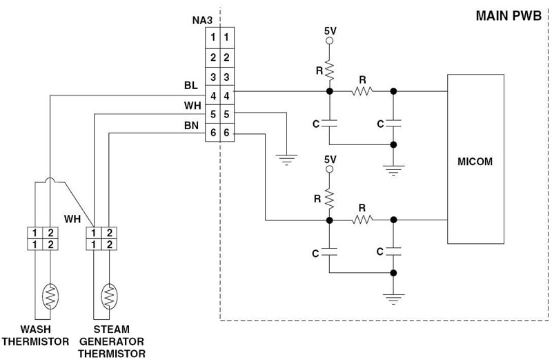
Use an ohmmeter to check the resistance of the sensor when it is disconnected from the circuit.
Wash Thermistor
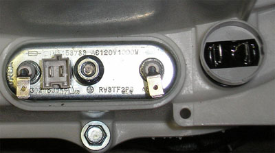 |
Test the resistance across terminals 1 and 2.
39.5 k ohms ± 5% at  86° (30° C)
26.1 k ohms ± 5% at 104° (30° C)
12.1 k ohms ± 5% at 140° (30° C)
 8.5 k ohms ± 5% at 158° (30° C)
 3.8 k ohms ± 5% at 203° (30° C)
 2.8 k ohms ± 5% at 221° (30° C)
|
Steam Generator Thermistor
The thermistor is located on the top of the steam generator. You can check it at the connector there.
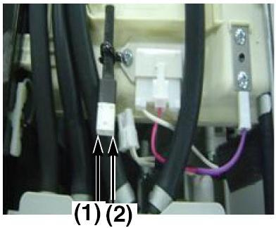 |
Test the resistance across terminals 1 and 2.
39.5 k ohms ± 5% at  86° (30° C)
26.1 k ohms ± 5% at 104° (40° C)
12.1 k ohms ± 5% at 140° (60° C)
 8.5 k ohms ± 5% at 158° (70° C)
 3.8 k ohms ± 5% at 203° (95° C)
 2.8 k ohms ± 5% at 221° (105° C)
 2.1 k ohms ± 5% at 241° (116° C)
 1.4 k ohms ± 5% at 266° (130° C)
 1.0 k ohms ± 5% at 293° (145° C)
 0.7 k ohms ± 5% at 320° (160° C)
 0.4 k ohms ± 5% at 356° (180° C)
|
Back to the list
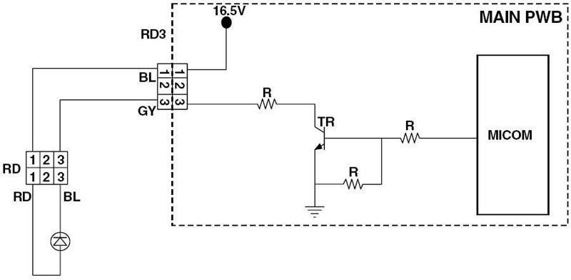
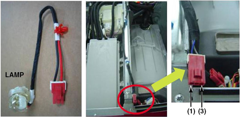
DRUM LAMP
Back to the list
BALANCE RING
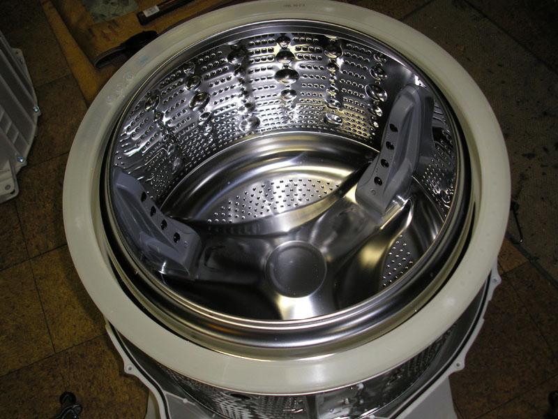
Another part of the anti-vibration system is the balance ring attached to the front of the drum. This balance ring contains several heavy steel spheres as counterweights and is filled with a viscous fluid. When the tub spins, the spheres drift naturally and slowly to a position opposite the out-of-balance load to compensate. The vibration sensor detects the vibration generated by this out of balance load and limits the velocity of the drum until the spheres have had time to regulate themselves. As the vibration is eliminated, the control board allows the motor to increase to full speed. This system eliminates the need for the SpinSense™ system that was included on earlier machines.
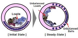 |
Diagram of the balance ring assembly showing the redistribution of the counterweights as they are opposite the load within the drum.
|
Back to the list
Questions? Comments! Concerns? Report an error? Let us know! An e-mail should solve the problem.


