
Questions? Comments! Concerns? Report an error?
Let us know!
An e-mail should solve the problem.
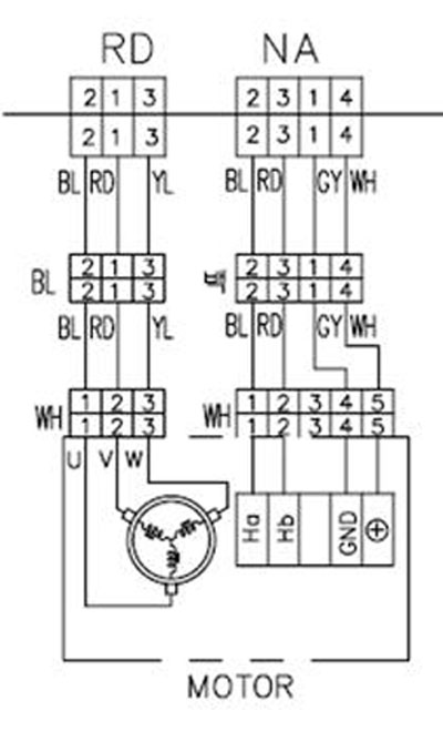
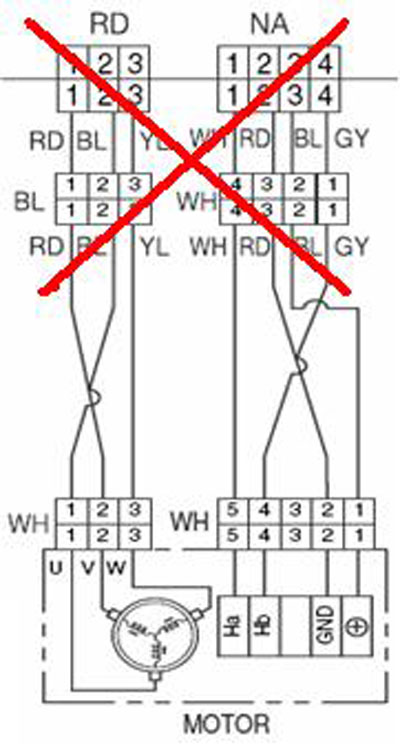
Check the wiring diagram for your machine. The wiring diagrams on some washing machines were incorrect in showing the hall sensor wiring. The error involves wiring terminal designation and color codes. See the diagrams below.
The correct wiring terminal colors are:
White is (+) Gray
is (-)
Red is Hb Blue
is Ha.
The correct version is shown left and the incorrect version is shown right.

|

|
Pay particular attention to the color codes and the position numbers in the connectors. This will be critical when taking voltage and resistance readings to determine component malfunction.
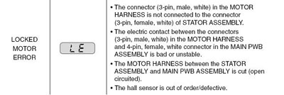
Hall Sensor testing methods are now available on the following pages when LE error code troubleshooting says “hall sensor is out of order or defective.”

|

|
 Part No. 6501KW2002A |
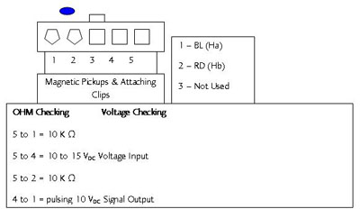
Hall Sensor Testing The hall sensor can be tested from the control board, the midway connector, or at the hall sensor itself. The midway connector is at the lower left as you face the back of the machine. There are two connectors; one with red, white, blue and gray wires for the hall sensor, and one with red, blue, and yellow wires for the motor. Do NOT try to test the voltages on the motoe lines. It runs on 310 VDC Volts and the shock could be fatal. Resistance Testing the Hall Sensor If tested off the stator using the diagram above, check the resistors from pin 5 to pin 1 and from pin 5 to pin 2. If the hall sensor is good, it should measure approximately 10 K ohms from pin 5 to pin 1 and 10 K ohms from pin 5 to pin 2. If either test indicates an open circuit (infinity), the hall sensor is defective and must be replaced. |
1. Unplug the power cord.
2. Remove the rear washer panel.
3. Locate the hall sensor connector on the stator behind the rotor.
4. Place the meter leads on terminals 5 and 4, white and gray.
5. Plug in the power cord, close the door, and press the power button.
DO NOT PRESS START!
6. You should measure 10 to 15 VDC. If 10 to 15 VDC is present, the control board is OK! If not, follow the testing output voltages on control board in next section.
7. To measure output signal voltage from the hall sensor, carefully move test leads to terminals 4 (gray) and 1 (blue). Rotate the motor rotor slowly by hand. It should read a pulsing 10 VDC. If 10 VDC is measured from pin 4 to pin 1, move the lead on the blue wire to the red wire, terminal 2. Repeat rotating motor rotor slowly by hand. It should read a pulsing 10 VDC.
8. If pulsing 10 VDC is measured from pin 4 to pin 1 and pin 4 to pin 2, the hall sensor is OK! If either test netted only 9 to 10 VDC without changing (no pulsing) the hall sensor is likely defective. Turn the washer off and disconnect power by unplugging the washer. Check the resistances of the hall sensor as outlined in Resistance Testing The Hall Sensor to verify failure of the hall sensor.
Control board output and hall sensor input voltages can be measured with the connector connected to the board and the machine operating. Also, these voltages can be measured by placing the meter leads on the desired terminals and spinning the tub briskly with the power cord disconnected.
• White to Gray – 10 to 15 VDC
• Gray to Blue – pulsing 10 VDC
• Gray to Red – pulsing 10 VDC
NOTE: If 10 VDC from gray-to-blue or gray-to-red does not change (pulse), that resistor is open! Confirm by disconnecting the power, disconnecting the hall sensor connector on the main board, and check the resistance of that individual circuit!
With power disconnected and the connector disconnected, the test the resistance at the hall sensor.
• White to Blue – 10 K ohms
• White to Red – 10 K ohms
Note: Resistance values are approximate; if either resistance check shows an open circuit (infinity), the wiring harness is open or the hall sensor is defective. Test both separately to determine the exact location of the failure!
 |
The potting epoxy has been removed to show the printed circuit board and its components. |
1. Unplug the power cord.
2. Remove the rear control panel cover.
3. Remove the top plate.
4. Remove the main board from the rear cabinet corner.
5. Identify the hall sensor connector on the main board, using the wiring diagram and wire colors as your guide.
6. Plug in the power cord, close the door, and press POWER.
DO NOT PRESS START!
7. Place the meter leads on the WHITE and GRAY wires. The reading should be between
10 ~ 15 VDC output from the main board to the hall sensor. If 10 ~ 15 VDC are not observed, the main board is defective.
8. Place the meter leads on the BLUE and GRAY wires. Turn the motor rotor slowly by hand. The reading should be a pulsing 10 VDC. Place the meter leads on the RED and GRAY wires. Turn the motor rotor slowly by hand. The reading should be a pulsing 10 VDC.
If both of these tests measure a pulsing 10 VDC, the hall sensor and wiring harness are OK. If either test measures 9 ~ 10 VDC but does not pulse or change, the hall sensor has failed and must be replaced.
If either test measures 0 (zero) voltage, check the RED and BLUE wires for continuity. Repair or replace the wiring harness as necessary.
Questions? Comments! Concerns? Report an error?
Let us know!
An e-mail should solve the problem.