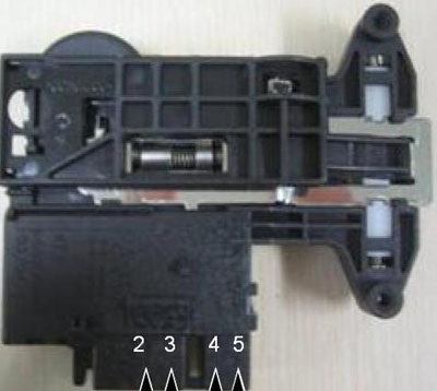
Test results at 77° F (25° C)
2 to 3 700 ~ 1,500 ohms
3 to 4 60 ~ 90 ohms
4 to 5 (infinity)
2 to 4 120 VAC (input voltage)
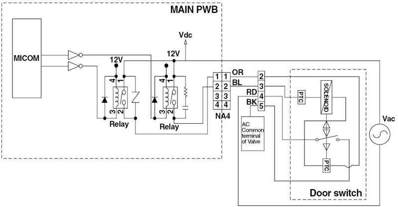
The door lock switch assembly includes a heating PTC, a bimetal, a protection PTC, and a solenoid. The assembly locks the door during the wash cycle and under certain other conditions, such as high temperatures.

When the system is energized through terminals 2 and 4, the PTCs begin heating. Before the solenoid operation is activated, the cam forces the system to the OFF position. One impulse through terminals 3 and 4 locks the door. The lock is detected by the main board when terminals 4 and 5 are closed.
When the machine is paused, the main board sends an impulse to terminals 3 and 4 and rotates the cam to the open position. The maximum number of impulses is 3. Upon the 4th impulse, the cam reverts to the locked position.
 |
Test results at 77° F (25° C) 2 to 3 700 ~ 1,500 ohms 3 to 4 60 ~ 90 ohms 4 to 5 (infinity) 2 to 4 120 VAC (input voltage) |
 |
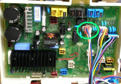
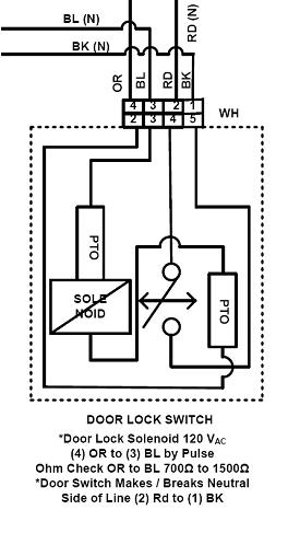
At the connector on the main board, the wires are:
OR ORANGE Door Switch (N) |
 |
The door switch solenoid operates by a pulse of 120 VAC between pins 3 and 4. With the switch out of the circuit, read the resistance between pins 3 and 4 (ORANGE and BLUE,) which should be 1,100 ohms ± 400 . The door switch makes or breaks NEUTRAL between pins 1 and 2 (RED and BLACK.) |
Questions? Comments! Concerns? Report an error? Let us know! An e-mail should solve the problem.