 |
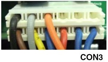
Check CONNECTOR 3. Unplug it and check for bent pins and broken wires. Replace the connector. |
 |
Enter TEST MODE 1.
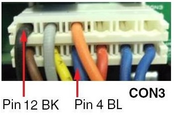
Measure the voltage to the compressor across PIN 4 and PIN 12 of CONNECTOR 3. It should be approximately 115 VAC, the same voltage as the wall outlet. If not, replace the MAIN BOARD. |
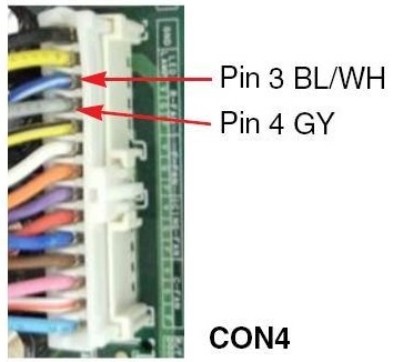 |
Measure the voltage across PIN 3 and PIN 4 of CONNECTOR 3. (Pin 3 BK/WH wire and Pin 4 GY wires) It should be 12 ~ 16 VDC. If not, replace the MAIN BOARD. |
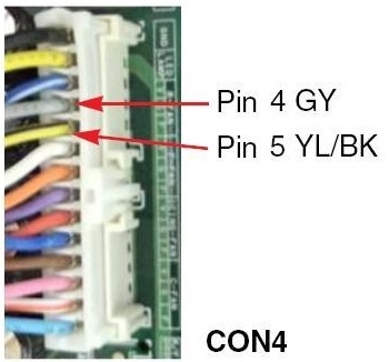 |
Read the feedback voltage across PIN 4 and PIN 5 of CONNECTOR 4. (Pin 4 GY wire and Pin 5 YL/BK wires) It should be between 1 and 4 VDC. If not, replace the MAIN BOARD. |
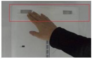 |
Still in TEST MODE 1, does cold air come out of the top of the MULTI-DUCT? If not, check the damper. In TEST MODE 1, the fan should run continuously and you should feel the air flow. |
 |
Enter TEST MODE 2. The cold air should stop coming out of the MULTI-DUCT. If the airflow doesn't stop, check the damper. |
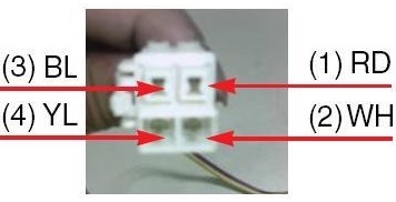 |
Remove the connector to the damper at the base of the MULTI DUCT.
Read the resistance across PIN 1 and PIN 4 (RD and YL wires). It should be 373 ~ 456 ohms. If not in spec, replace the damper. Read the resistance across PIN 2 and PIN 3 (WH and BL wires). It should be 373 ~ 456 ohms. If not in spec, replace the damper. |
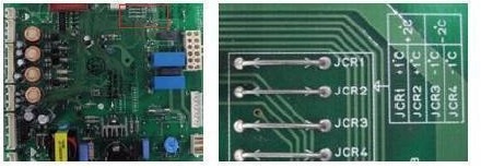 |
After taking the refrigerator out of test mode, adjust the MAIN BOARD for temperature compensation. Cut JUMPER 3 and Jumper 4 to adjust the temperature downward by 1° or 2° C (1.8° or 3.6° F). |
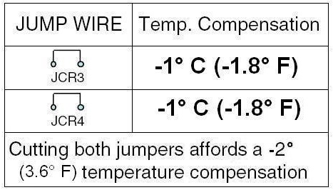 |
Cutting both jumpers affords the full -2° C temperature compensation.
A similar adjustent can be made to adjust the refrigerator temperature upward. Cut JUMPER 1 and Jumper 2 to adjust the temperature upward by 1° or 2° C (1.8° or 3.6° F). |
Questions? Comments! Concerns? Report an error?
Let us know!
An e-mail should solve the problem.