 |
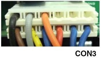
Chck CONNECTOR 3 on the MAIN BOARD. Power off the refrigerator. Unplug the connector. Check for bent pins and broken wires. Replace the connector into the MAIN BOARD. |
 |
Power up the refrigerator
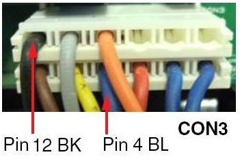
Enter TEST MODE 1. Read the voltage across PIN 4 and PIN 12 of CONNECTOR 4 (BL and BK wires). It shpould be approximately 115 VAC, the same as at the wall receptacle. |
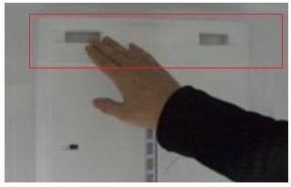 |
With the refrigerator running, check for air flow at the top of the MULTI-DUCT. Open the door and press the DOOR SWITCH. The light should go OFF and the fan should come ON. With the door open and the switch not touched, the light should go ON and the fan should come OFF. |
 |
Enter TEST MODE 2. Is cold air flowing out of the top of the MULTI-DUCT? If not, replace the damper. |
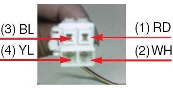 |
Check the DAMPER. Unplug the DAMPER CONNECTOR.
Read the resistance across PIN 1 and PIN 4. It should be between 373 ~ 456 ohms. Read the resistance across PIN 2 and PIN 3. It should be between 373 ~ 456 ohms. If either is out of spec, replace the damper. |
 |
Enter TEST MODE 3.
Read the voltage across PIN 4 and PIN 12 of CONNECTOR 4 (BL and BK wires). It should be between 0 and 2 VAC. |
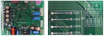 |
After taking the refrigerator out of test mode, adjust the MAIN BOARD for temperature compensation. Cut JUMPER 3 and Jumper 4 to adjust the temperature upward by 1° or 2° C (1.8° or 3.6° F). |
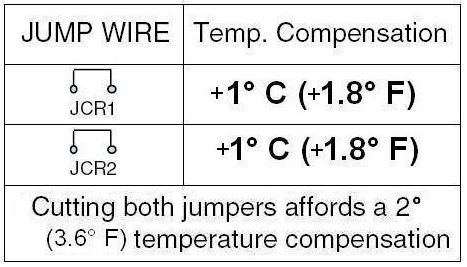 |
Cutting both jumpers affords the full -2° C temperature compensation.
A similar adjustent can be made to adjust the refrigerator temperature upward. Cut JUMPER 3 and Jumper 4 to adjust the temperature downward by 1° or 2° C (1.8° or 3.6° F). |
Questions? Comments! Concerns? Report an error?
Let us know!
An e-mail should solve the problem.