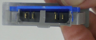
The door switches determine whether the doors are opened or closed. When a door is opened, appropriate interior lighting is switched on by the microprocessor, which also operates various fans and dampers.
 |
Remove the switch from its housing by pressing the tabs on either end of the switch and pulling it out of the housing. Disconnect it from the wiring harness.
The door switches determine whether the doors are opened or closed. When a door is opened, appropriate interior lighting is switched on by the microprocessor, which also operates various fans and dampers. |
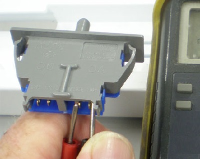 |
Check the resistance between terminals 1 and 2, and between terminals 3 and 4. With the switch plunger pushed in, there should be infinite resistance. With the plunger released, there should be 0 ohms resistance. |
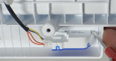 |
Remove the switch from its housing by pressing the tabs on either end of the switch and pulling it out of the housing. Disconnect it from the wiring harness.
The door switches determine whether the doors are opened or closed. When a door is opened, the appropriate interior lighting is switched on by the microprocessor, which also operates various fans and dampers. |
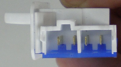 |
Check the resistance between terminals 1 and 2, and between terminals 3 and 4. With the switch plunger pushed in, there should be infinite resistance. With the plunger released, there should be 0 ohms resistance. It is simply two single-pole single-throw switches. |
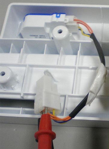 |
The normally closed (NC) Upper Freezer Door Monitor is 5 VDC Orange to Orange. It connects to BLACK and SKY BLUE (BK and SB) at CON 6 Pins 5 and 6 on the main board.
With the switch pressed, orange to orange should show infinite resistance. (Door closed, switch open, light off.) |
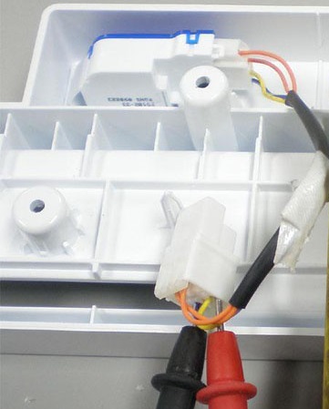 |
With the switch pressed, read the resistance across the WHITE with BLUE TRACER and YELLOW wires. It should show infinite resistance. (Door closed, switch open, light off.) |
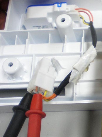 |
The normally closed upper freezer door switch should read infinite resistance across blue/white tracer (12 VDC) and the yellow wire connects to the red (Freezer LED module.) |
Questions? Comments! Concerns? Report an error?
Let us know!
An e-mail should solve the problem.