

Schematic for Defrost Heater and Fuse
 |
Check for error message Er dH. |
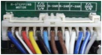 |
Check connector 3 on the main board. Re-seat it if necessary. |
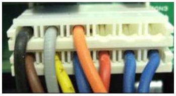 |
Check connector 6 on the main board. Re-seat it if necessary. |
 |
Enter the TEST 3 mode.
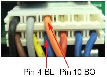
The defrost heater relay should energize. Check the voltage across pins 4 and 10 of connector 3. The voltage should be 120 VAC. If not in specification, replace the MAIN BOARD. Pin 4 is BLUE; pin 10 is BURNT ORANGE. |
 |
Reset (exit) the TEST 3 mode.
The defrost heater relay should release. Check the voltage across pins 4 and 10 of connector 3. The voltage should be 0 VAC. If not in specification, replace the MAIN BOARD. Pin 4 is BLUE; pin 10 is BURNT ORANGE. |
 |
Unplug the refrigerator.
Check the resistance across pins 4 and 10 of connector 3. The resistance should be between 34 and 42 ohms. If not in specification, replace the MAIN BOARD. Pin 4 is BLUE; pin 10 is BURNT ORANGE. |
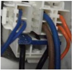 |
Remove the back cover and check the 3-part connector in the freezer above the evaporator. If any part of the connector is loose, unplug all of it and re-insert the plug(s). |
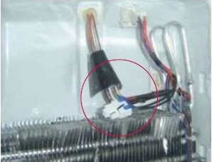 |
Unplug the heater element and check the resistance. It should be between 34 and 42 ohms. If it is not within specification, replace the heater. The BLACK wires indicate the connector for the heater. |
 |
Check the continuity of the fuse. If the fuse is blown, replace it. The BLUE and BROWN wires indicate the connector for the fuse. |
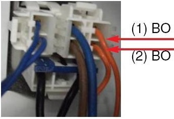 |
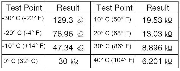
Check the resistance of the defrost sensor. See the chart below for the resistance at various temperatures. If it is not within specification, replace the sensor. The BURNT ORANGE wires indicate the connector for the fuse. |
Questions? Comments! Concerns? Report an error?
Let us know!
An e-mail should solve the problem.