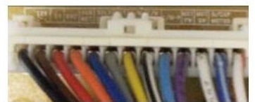
Check CONNECTOR 2 on the DISPENSER. Reconnect if necessary. Check for bent or missing pins and broken crimps.
 |
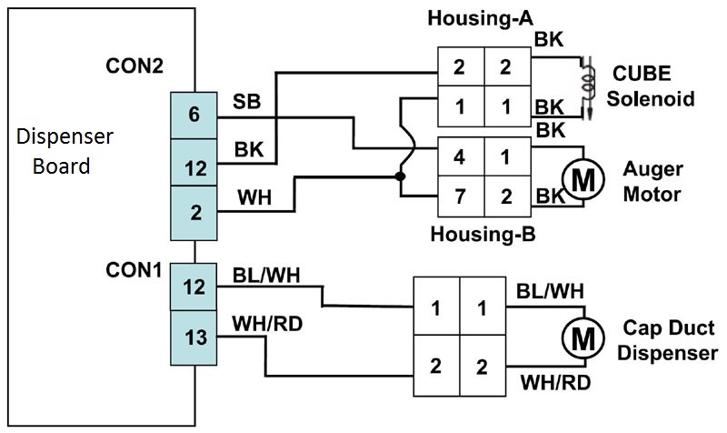
Check CONNECTOR 2 on the DISPENSER. Reconnect if necessary. Check for bent or missing pins and broken crimps. |
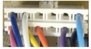 |
Check CONNECTOR 3 on the MAIN BOARD. Reconnect if necessary. Check for bent or missing pins and broken crimps. |
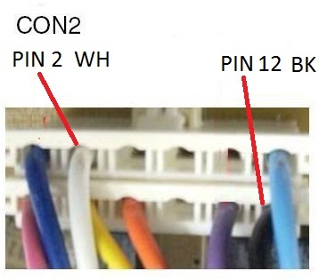 |
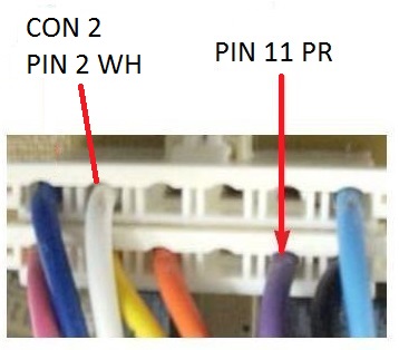
In CUBE MODE, read the voltage across pins 2 and 6. It should be 120 VAC when the dispenser switch is pressed to deliver cubes, and 0 ~ 2 VAC in standby mode. If it is out of specification, replace the dispenser board. |
 |
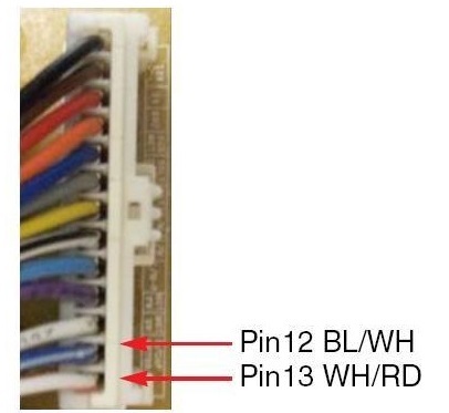
In CUBE MODE, read the voltage across pins 1 and 11. It should be 120 VAC when the dispenser switch is pressed to deliver cubes, and 0 ~ 2 VAC in standby mode. If it is out of specification, replace the dispenser board. |
 |
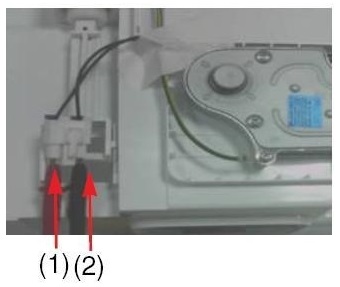
In CUBE MODE, read the voltage across pins 12 and 13 of connector 1. It should be 12 VDC when the dispenser switch is pressed to deliver cubes, and 0 VDC in standby mode. If it is out of specification, replace the dispenser board. |
 |
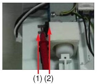
Unplug the connector to the auger motor and read the resistance. It should be between 2.4 and 4.0 ohms. It it is out of specification, replace the auger motor. |
 |
Unplug the connector to the cube solenoid and read the resistance. It should be between 32 and 40 ohms. If it is out of specification, replace the cube solenoid. |
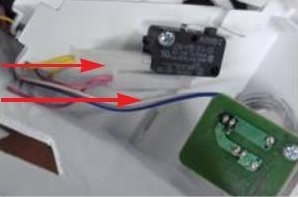 |
Unplug the connector to the microswitch and read the resistance. It should be 0 ohms when the switch is pressed, and infinite resistance in standby mode. If it is out of specification, replace the microswitch. |
Questions? Comments! Concerns? Report an error?
Let us know!
An e-mail should solve the problem.