The sealed burner 30" gas range has a service test mode that can be utilized by the service technician in order to test certain oven components or functions. The selected components or functions will help the service technician to quickly identify failed or improper operation of the range.
Testing is accomplished through built-in test procedures. Unplugging components for testing can damage component connections. The range must be powered down (unplugged) before entering the test mode.
Test Mode Entry:
1. Unplug the range for a minimum of 15 seconds.
2. Power up the range (all segments in the display and the control panel selections illuminate), and wait until the time of day is flashing.
3. Touch COOK TIME, DELAY START, and 8 simultaneously. The display will shows the TEST on the convection model or SAVE on the non-convection model.
The test will time out in approximately 4½ minutes.
Repeat the test mode entry sequence to continue.
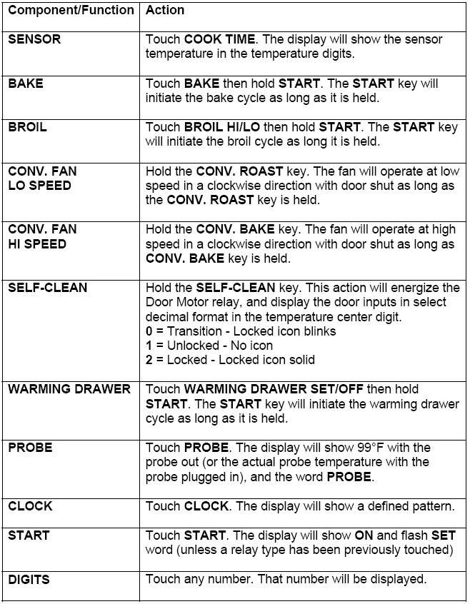
See TEST MODE CHART, following.
The oven may stop operating but not give an F-code on the display immediately. Generally, a fault must exist continuously for 5 minutes before an F code is recorded (F2 is sooner). F-codes are stored in non-volatile EEPROM memory until the same fault occurs twice consecutively. After that, the F-code will be displayed. F-codes can be recalled by pressing together TIMER, CLOCK, and 9.
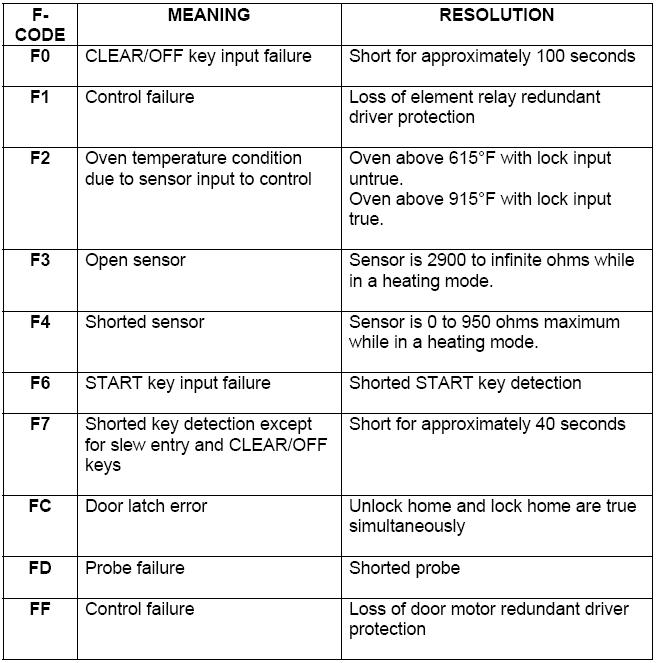
Multiple fault codes may be displayed. The latest fault code will appear on the right of the display. While F-codes are displayed, pressing 8 and 6 simultaneously will clear the codes from the memory. Clear the fault code after the failure has been corrected.
The key panel and ERC are separate components but must be tested together. Press each pad on the key panel followed by the START pad. If the key panel is functioning properly, the following should occur:
BAKE, CONV. BAKE, CONV. ROAST, BROIL HI/LO, COOK TIME,
DELAY START, WARMING DRAWER SET/OFF, SELF CLEAN, CLOCK,
TIMER ON/OFF, and CONTROL LOCKOUT Modes
- Audible tone plus display showing mode of operation selected.
CLEAR/OFF
- Audible tone and display shows time of day.
PROBE
- Audible tone and response if meat probe is plugged in
NUMBERS
- Audible tone. (Can be used only after another function has been selected.)
The operation of the warming element is controlled by user settings and the ERC. One of three warming drawer heat settings can be selected. After a pre-determined timed preheat period, cycling of the element is controlled by the ERC with a four-minute duty cycle.

The broil burner heats the oven to approximately 775°F (413°C). After 775°F (413°C) is reached, only the bake burner maintains clean temperature of approximately 815°F (435°C) center temperature. The convection fan does not operate in the clean cycle.
The convection fan is operated by a 2-speed non-reversing motor. The fan motor operates on low speed during convection bake and on high speed during convection roast.
The convection fan does not operate during preheat or self-clean.
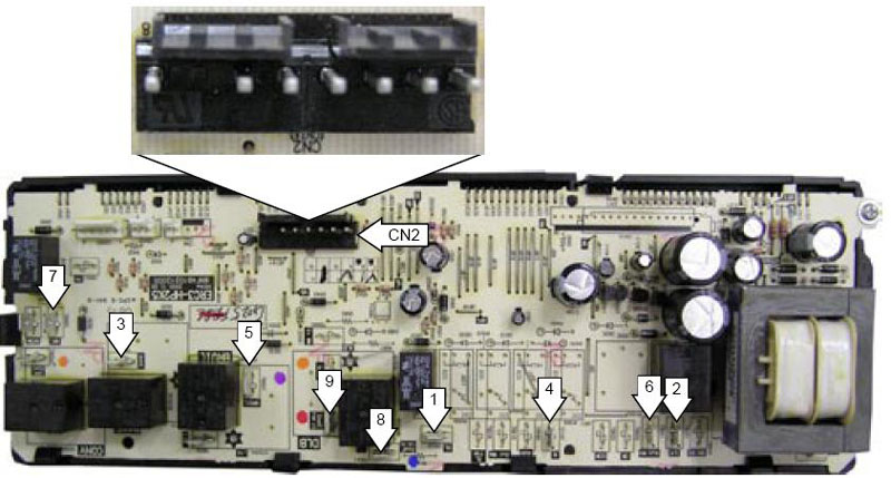
1. Oven light
2. Line
3. Bake
4. Neutral
5. Broil
6. Warming drawer
7. Lock motor
8. Convection Fan High
9. Convection Fan
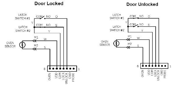
Pin 1 Probe
Pin 2 Ground
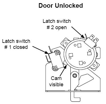
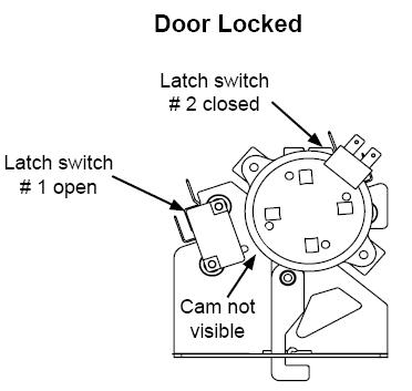
Pin 3 Unlock (Latch switch #1)
Pin 4 Lock (Latch switch #2)
Pin 5 Common
Pin 6 VDD (Sensor)
Pin 7 Blank
Pin 8 Oven (Sensor)
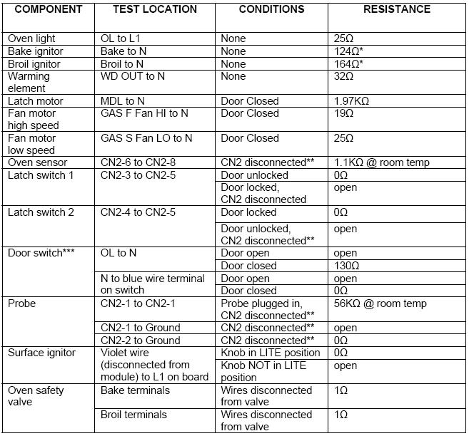
* Resistance will vary widely with the temperature of the ignitor. If the circuit tests open, repair the wiring or replace the ignitor.
** CN2 connector must be physically separated from the board
*** Alternate method - Remove the door switch. Leave the wire harness connected to the switch.
Check white to red wire:
Switch plunger out = 0 ohms
switch plunger in = approximately 130 ohms.
Check white to blue wire:
Switch plunger out = open
switch plunger in = 0 ohms.
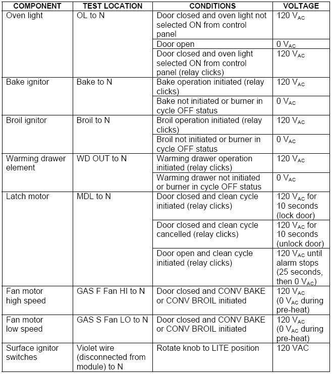
See Lock Motor and Door Latch Switch Circuit Information for door switch function explanation.
1. Unplug the oven.
2. Locate and disconnect the wire harness from the CN2 location on the ERC (main board).
3. Make resistance measurement from the side of the wire harness connector with exposed terminals.
4. If abnormal reading is observed, check leads in the wire harness connector. If any variation, repair or replace wire harness.

Questions? Comments! Concerns? Report an error?
Let us know!
An e-mail should solve the problem.