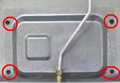
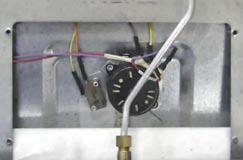
The door latch assembly consists of a lock motor, cam and switch assembly, lock hook, and mounting plate. It will be supplied as a complete assembly. The door latch assembly is located under the main top in a recess that is concealed by a metal cover.
To replace the door latch assembly:
1. Remove the oven door.
2. Remove the main top.
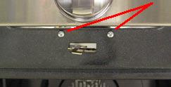
3. Remove the two ¼” hex screws that attach the shield to the top right side of the manifold panel.

4. Remove the four ¼” hex screws that hold the latch assembly cover in place.
5. Remove the cover.

6. Mark and disconnect the wiring from the latch assembly.

7. Remove the two T-15 Torx® screws that attach the latch assembly to the frame and slide the assembly out of the recess.

The lock motor circuit and the door latch switch circuit control the locking and unlocking of the door.
The lock motor is energized when the SELF CLEAN cycle is initiated with the door closed. The lock motor circuit applies voltage (120 VAC) to the lock motor. This circuit is from the motor door lock relay (MDL location on ERC), to the lock motor, through the door switch to neutral.
For this circuit to be complete, the lock motor circuit must be energized by the ERC and the door must be closed. An open oven door results in LOCKED flashing in the display and alarm sounding after the control has been programmed for clean and START has been selected.
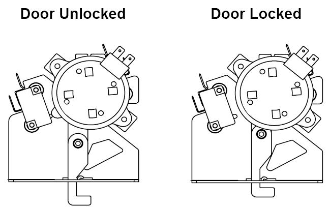
The door latch switch circuit signals the control if the lock motor is in the unlocked or locked position or somewhere in between (transition). There are two latch switches operated by the cam located below the lock motor.
The door latch switch circuit is from the ERC, through one of the latch switches (switch 1 for unlocked or switch 2 for locked) back to the ERC. If neither switch is closed, and the oven temperature is below 450°F (232°C) the ERC will energize the lock motor circuit until the correct switch closes to complete the circuit. (If circuit to the correct switch is open, the lock motor will run continuously with the oven below 450°F (232°C).
The cam on the motor performs two functions:
• Positions the lock hook in the door to prevent opening during the CLEAN operation.
• Operates the latch switches which tell the control if the door is unlocked or locked and ready for CLEAN operation.
When the door is either being locked or unlocked, both latch switches will be in the open position.
The movement of the cam has also closed lock switch 2 which signals the control that the door is locked. The control then removes power from the lock motor circuit by de-energizing the lock relay. The lock motor stops and lock switch 2 is held closed by the cam through the clean cycle. The word LOCKED stops flashing and remains illuminated in the display. The word ON remains illuminated in the display. During the Clean Cycle, the oven will cycle to maintain an average clean temperature of 815° F (435° C).
Programming the Clean Cycle:
Press SELF-CLEAN pad. 4 hours and 20 minutes (4:20) appears on the time display. (Cleaning time can be changed from the 4 hour and 20 minute starting point by pressing the SELF-CLEAN pad a second time.)
After START has been pressed, the word ON illuminates in red and the word LOCKED flashes to indicate the cycle has begun.
Locking the Door:
After programming the clean cycle and pressing the START pad, the control energizes the lock relay. Voltage (120 VAC) is applied to the lock motor circuit. The oven door must be closed before lock motor can run. LOCKED will flash and control will beep until the door is closed.
The lock motor begins to revolve and turns a cam mounted to the motor shaft.
The word LOCKED will flash on and off on the display while the lock motor is in motion.

As the cam revolves about ½ revolution (approximately 12 seconds), it has moved the lock hook into a corresponding slot in the oven door which secures the door. The words LOCKED and ON with the clean cycle time remaining will be displayed.
Questions? Comments! Concerns? Report an error?
Let us know!
An e-mail should solve the problem.