This appliance must be properly grounded. Wiring must conform to the National Electrical Code (NEC) and all local codes.
Ground path resistance 0.10 W Max.
Insulation resistance 250 KW Min.
This range is designed to operate at a pressure of 5 inches of water column on natural gas or 10 inches on LP (propane or butane).
 |
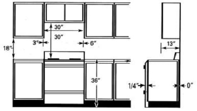
This drawing shows the minimum clearances for the gas range. The 30” requirement between stovetop and cabinet bottom allows sufficient space to the installation of a standard over-the-range microwave oven. |
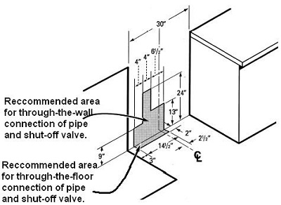 |
This drawing shows the dimensions and suggested placement of the electrical and gas connections behind the range. The template makes it easy to locate all items properly. |
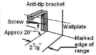 |
Be sure to install the anti-tip bracket. This prevents tipping the range in the event someone stands on the door or otherwise puts the range off balance. Use the installation template to locate the wall bracket; then, attach the bracket to the wall with a large wood screw. |
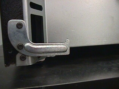 |
When the range is pushed back into place, the bracket attached to the range will be positioned under the wall bracket and it will keep the range from tipping. |
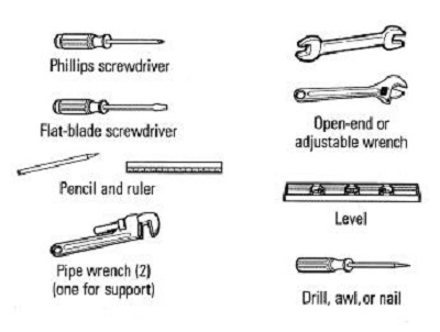 |
For the most part, ordinary hand tools are sufficient for installing the range. It will be necessary to check the incoming gas pressure and to regulate it if it is out of specification. |
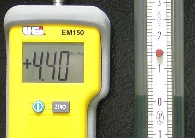 |
A manometer is essential for proper regulation of gas pressure and diagnosis of supply and combustion problems. You can use either a digital manometer or the older style slack-tube manometer. |
Questions? Comments! Concerns? Report an error?
Let us know!
An e-mail should solve the problem.