Sharp edges are exposed when servicing the oven. Wear Kevlar® gloves or an equivalent protective hand cover.
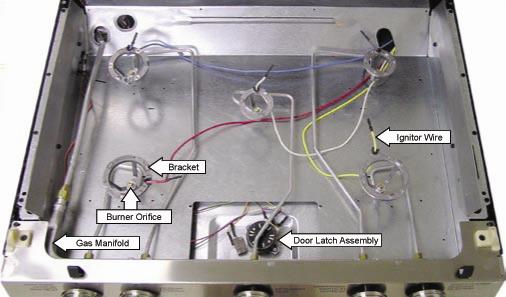
To remove the door, open it to the first stop near the vertical (closed) position. Lift the door and pull it straight up.
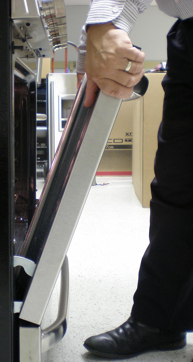
Hold the door by the top corners in a nearly vertical position (similar to removal in the previous step.) Guide the hinge arms into the door slots and push the door onto the arms firmly. Close the door and check for alignment. Operate the door a couple of times to make sure it opens and closed properly and without binding.
If the door cannot be closed properly, it is not seated on the hinge arms.
DRAWER REMOVAL
Pull the drawer out all the way to the stop. There are tabs in the drawer rails. Lift the left tab and push down the right tab to pull the drawer off the rail.
DRAWER REPLACEMENT
To replace the drawer, place the rails into the slides and push the drawer into the range.
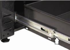
Each track is attached to the range with a Phillips screw and two tabs. To remove the track, remove the screw from the front of the track and pull the slide out. Lift the track slightly and twist it toward the center of the range to disengage the front tab. Then pull the track forward to release it.
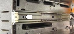
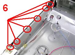
Reminder! Unplug the range before servicing the element! You’ll need to remove the warming drawer to service the heating element. Remove the two T 15 Torx® screws that hold the terminal cover. The element is attached to the bottom of the range with six clips held by ¼” hex-head screws.

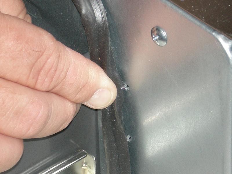
The gasket is held by several small, wire clips that are supplied already formed into the gasket. Use needle-nosed pliers to remove the clips. This gasket forms a seal around the top and sides of the drawer.
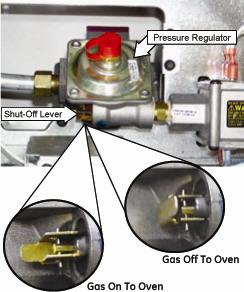
NOTE: The gas shutoff valve shuts off the gas to the oven ONLY and has no effect on the surface burners. This shutoff valve is accessible from the inside of the range after the warming drawer is removed.
The shutoff valve allows servicing the oven burners without having to pull the range out and shut off the gas main.
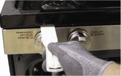
Remove the grates, burner caps, burner heads, igniters, and the T 15 Torx® screws from the cooktop.
Insert a putty knife under the edge of the main top press the clips and allow removal of the main top.
1. Remove the range from its installation.
2. Remove the door.
3. Remove the warming drawer.
4. Remove the main top.
5. Remove six Phillips screws from the top of the side panel.
6. Remove the Phillips screw from the front panel under the hinge.
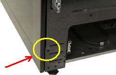
7. Remove four ¼” hex head screws from the back edge of the side panel.
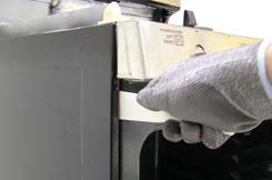
8. Slide a putty knife into the side panel under the manifold panel and gently pry the side panel off the snap fastener.
1. Remove the range from its installation.
2. Remove the door.
3. Remove the warming drawer.
4. Remove the side panel.
5. Note the position of the hinge spring and the paint indicator.
Remove the hinge spring.

6. Remove the E-clips from the hinge pin and remove the pin.

7. Remove the two ¼” hex head screws that attach the hinge to the frame.

8. Position the top of the hinge body into the notch in the hinge arm (see photo) and rotate the hinge body clockwise to remove.

The doors can be separated into two assemblies: (1) the outer assembly, consisting of the handle, vent trim, outer glass, and frame; and (2) the inner assembly, consisting of the inner panel, gasket, glass panels, and insulation. The inner and outer assemblies are held together by two T 20 Torx® screws in the top corners and four ¼” hex head screws across the bottom edge.
The gasket is held in place between the inner and outer sections of the inner door panel.
1. Remove the oven door.
2. Place the door inside up on a padded surface.
3. Remove the two Torx T 20® screws from the top corners of the inner panel. Remove the four ¼” hex head screws from the bottom of the door and remove the inner assembly.
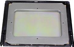
4. Place the inner assembly inside up on a padded surface.
5. Remove the four ¼” hex head screws, the inner door panel, and the insulation.
6. Remove the four ¼” hex head screws from the outer frame and carefully lift off the outer frame.
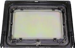
NOTE!
When replacing the gasket, be sure the gasket bead is positioned evenly and uniformly between the outer and inner sections of the inner door panel.
The probe outlet is near the top left corner of the oven.
1. Remove the two Phillips screws that attach the probe outlet to the oven.
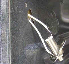
2. The outlet and wiring can be pulled out approximately 1½”.

When replacing the probe outlet, cut the wires as close to the end as possible. Then splice them to the new outlet using heat-resistant connectors.
Questions? Comments! Concerns? Report an error?
Let us know!
An e-mail should solve the problem.