 |
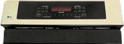
CONTROL PANEL1. Loosen but do not remove the two ¼” hex head screws at the top corners of the back panel. |
 |
2. From the front, remove the two T 15 Torx® screws that attach the bottom of the control panel to the back guard. |
 |
NOTE! To prevent damage to the control panel, put a piece of cardboard or a towel or blanket over the grates. |
 |
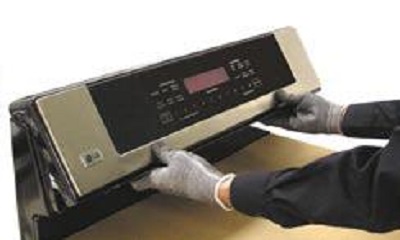
3. Grasp and pull the bottom of the control panel out about one inch and lift it off the top rear corner screws. |
 |
4. Carefully fold the control panel over the grates into the service position. |
NOTE!To avoid damage to the porcelain components, do not overtighten the screws. |
 |
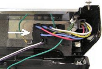
SPARK MODULEThe spark module is in the back guard and held in place by two plastic tabs, one on each side. Put the control panel into service position, and press either tab to remove the module. |
NOTE!Make a note of the wire positions before disconnecting the module. |
 |
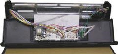
ELECTRONIC RANGE CONTROLTo access the electronic range control (ERC or main board), put the control panel into the service position. Remove the four Phillips screws (two on each side). Mark and label the wire locations before disconnecting the ERC.
1. Wire tie holding wire harness to ERC. |
| 3. Wiring harness to touch panel. |
 |
CONTROL PANEL AND TOUCH BOARD
The control panel and touch board are supplied as an assembly. If the touch board is damaged, the entire control assembly must be replaced.
|
Questions? Comments! Concerns? Report an error?
Let us know!
An e-mail should solve the problem.