Online Training Manual for LG Products - Adjust Gas Pressure - Surface Burners
REGULATING GAS PRESSURE
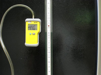 |
Correct gas pressure is essential for quick burner ignition, correct burner BTUH input, and to minimize the byproducts of combustions, such as carbon monoxide. The recommended regulated pressure for natural gas is 3.5 to 4 inches of water column. Likewise, for LP the recommended pressure is 10.5 to 11 inches of water column.
To measure the gas pressure, youll need either a digital or water (slack tube) manometer.
|
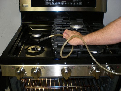 |
Measuring gas pressure can be easily accomplished at any of the 5 surface burners.
Remove a burner grate and one of the sealed burners. Then place the gas pressure measuring tube over the orifice.
With the pressure fitting over the orifice and the range unplugged, turn the surface valve to an open position and record the gas pressure.
If the gas pressure measured is incorrect, check the gas regulator cap position. If it is properly installed for the gas type (natural or LP), replace the regulator and retest pressure.
|
SAFETY VALVE and PRESSURE REGULATOR |
WARNING!
NOTE!
Before servicing the range, disconnect the power and the gas supply. Be sure the oven is absolutely cool.
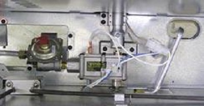
The pressure regulator and the safety valve are a combination unit (combi-valve) and must be replaced as an assembly.
|
 |
NOTE!
The combi-valve is front serviceable. The amperage should be between 3.3 and 3.6 amps at 3.0 to 3.3 VAC.
1. Remove the oven door.
2. Remove the warming drawer.
3. Remove the bake burner.
4. Remove the gas line connections at the valve. (The line by the regulator is 11/16 and the line by the oven shutoff safety valve is 9/16.)
5. Remove the 5 hex head screws that secure the combi-valve.
6. Remove the valve.
|
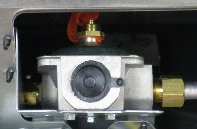 |
The regulator has an adjustment for converting the range from natural gas to propane (LP). The adjustment screw is marked to show which way is up for natural gas or propane (LP).
|
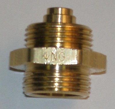 |
Note the marking that shows the short end to be installed for natural gas. On the other side, the arrow points toward the longer end for propane (LP).
Conversion includes changing or adjusting the orifices as well.
|
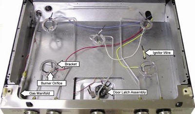
SURFACE BURNER ASSEMBLY
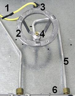 |
1. Ignitor wire
2. Bracket
3. Wire inlet
4. Orifice
5. Inlet tube
6. ½ fitting
|
 |
WARNING!
Shut off the gas to the range before proceeding!
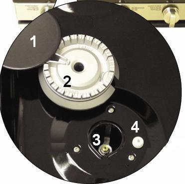
Each main top burner consists of:
1. Burner cap
2. Burner head
3. Orifice
4. Ignitor
5. Inlet tube (not visible, see photo above)
|
BURNER REMOVAL
1. Remove the maintop.
2. Remove the two ¼ hex head screws that attach the shield to the top right side of the manifold panel. (Omit this step if servicing the left front or left rear burner.)
3. Pull the ignitor wire out of the wire inlet bracket.
4. Use a 5/8 socket and extension to remove the nut that holds the bracket to the inlet tube and lift the bracket away.
5. Remove the ½ nut that secures the inlet tube to the valve.
MAIN BURNER ALIGNMENT
For proper operation of the burner, alignment of the orifice holder, orifice, and air/gas mixer tube must be correct. The alignment can be checked by placing
7 mm or 9/32 in. nut driver over the orifice to exaggerate the angle. The nut driver should stand straight, indicating the alignment and gas injection angle is correct. A slight downward pressure may be necessary to seat the nut-driver over the orifice-retainer ring. If an angle adjustment is necessary remove the burner cap, head, and bowl to inspect the orifice holder and the brackets that hold them in place. Adjust as necessary by carefully bending the supply tube. A misaligned burner may result in uneven flames around the burner head.
MAIN TOP BURNER FLAME ADJUSTMENTS
The top burners do not have air shutters and fixed, non adjustable orifices are used. If the flames blow off the burner or have yellow tips, check the following:
Gas pressure - 5 Natural gas or 10 LP gas.
Inspect orifice to be sure it is drilled on center and free of debris or burrs.
Be sure the correct size orifice is in the proper location.
Make sure the range was properly converted if on LP gas.
LOW FLAME SIMMER ADJUSTMENTS
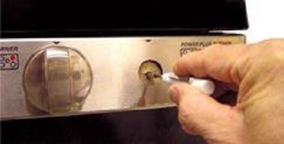 |
Remove the surface control knob and locate the adjustment screw in the center of the control valve shaft. A thin flat-blade screwdriver, approximately 3/32 across, is needed to access the screw. Turn the adjustment screw until the flame reaches the desired size.
|
TESTING BURNER FLAME STABILITY
TEST 1
Turn the knob from HI to LOW quickly. If the low flame goes out, increase the flame size and test again.
TEST 2
With the burner on LOW setting, open and close the oven door quickly. If the flame is extinguished by the air currents created by the door movement, increase the flame height and test again.
TEST 3
With 2 burners on HIGH setting, set a third adjusted burner on LOW. Turn the first knob from HI to LOW quickly. The third burner should stay lit.
MANIFOLD PANEL
 |
1. Remove the oven door.
2. Remove the main top.
3. Remove the surface burner valve knobs by pulling each knob straight out.
4. Remove the two ¼ hex head screws that attach the shield to the top right side of the manifold panel.
|

|
5. Remove the 2 Phillips-head screws and the 2 guides from the main top.
6. Remove the 4 Phillips-head screws that hold the front of the manifold panel to the gas manifold.
|
 |
7. Remove the three ¼ hex head screws from the bottom of the manifold panel.
8. Pull the manifold panel straight out from the range.
|
MANIFOLD BURNER VALVES
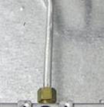 |
The manifold burner valves are located behind the manifold panel. Each valve is attached to the manifold by a single screw.
1. Turn off the gas supply.
2. Remove the manifold panel.
3. Using a ½-in. open end wrench, disconnect the burner inlet tube from the valve.
4. Remove the ¼-in. hex-head screw that holds the valve to the manifold.
5. Lower the valve from the manifold.
|
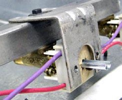 |
6. Remove the protective cover from the valve stem.
7. Remove the ignitor switch from the valve.
|
|
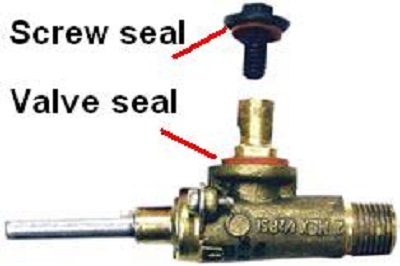
WARNING
Ensure the valve seal and the screw seal are carefully positioned before installing the valve.
|
IGNITOR SWITCHES
The ignitor switches are located inside the manifold panel and are attached to each maintop burner valve. The back of each switch is molded to conform to the front of the burner valve and is locked in place by 2 tabs. All switches are wired to a single harness and can be replaced separately.
NOTE!
To replace the ignitor switch for the left or right rear burner, it is necessary to remove the left or right rear burner valve from the gas manifold.
CAUTION!
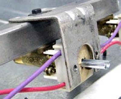 |
The 2 lock tabs on each ignitor switch are fragile. Tab breakage can occur if excessive release pressure is applied.
When replacing the ignitor switch for the left or right rear burner, remove the valve from the gas manifold.
1. Be sure the range is unplugged.
2. Remove the manifold panel.
3. Remove the protective cover from the valve stem.
4. Using a small flat blade screwdriver, carefully pry on the two release tabs and slide the switch off the valve stem.
|
NOTE!
When replacing an ignitor switch, cut the switch wires and splice the new switch using approved connectors and heat shrink tubing.
GAS MANIFOLD
WARNING!
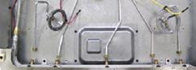 |
To remove the gas manifold:
1. Remove the maintop.
2. Remove the two ¼ hex head screws that attach the shield to the top right side of the manifold panel.
3. Remove the ½ nut that holds the inlet tube to each valve.
4. Using a 13/16 open-end or adjustable wrench, disconnect the gas inlet tube from the gas manifold.
5. Remove the left and right rear burner knobs then remove the four Phillips head screws from the front of the manifold panel.
6. Remove the two ¼-in. hex-head screws that attach the gas manifold to the range.
7. Remove the five burner valves from the gas manifold.
|
Questions? Comments! Concerns? Report an error?
Let us know!
An e-mail should solve the problem.


