Strip Circuits
Online Training Manual for LG Products - Electric Range Main Menu
STRIP CIRCUITS
• Before checking the oven circuitry, be sure to check the line voltage and the fuse or circuit breaker.
• Check for loose or incorrect wiring inside the range.
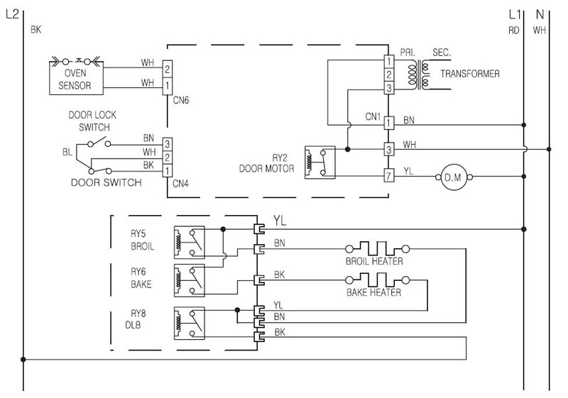
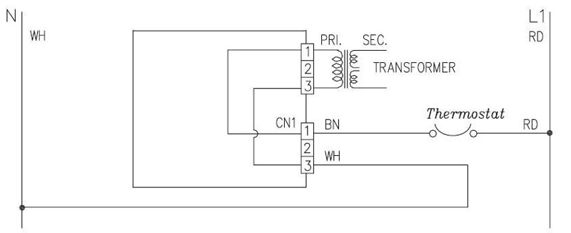
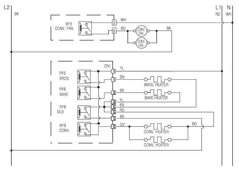
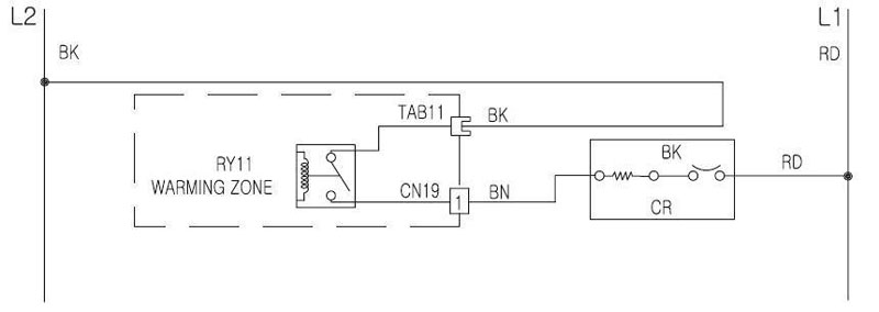
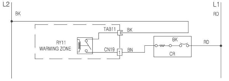
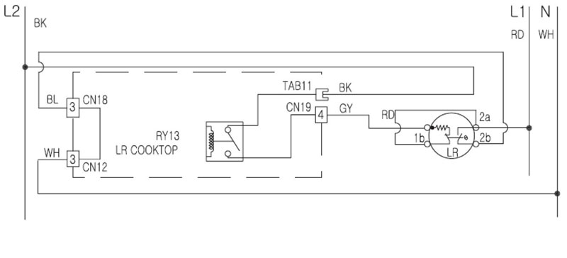
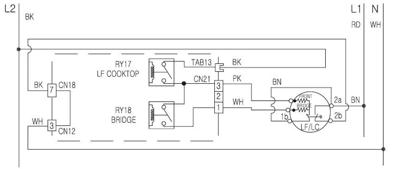
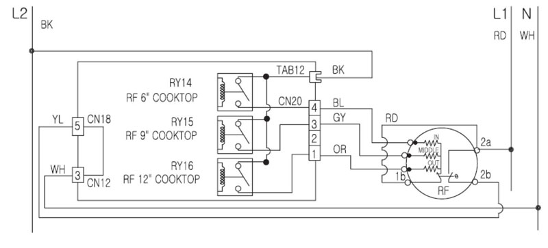
The following strip circuit diagrams are to aid the servicer in diagnosis and repair. The diagrams are shown in the ON position.
BAKE / COOK and WARM / PROOF
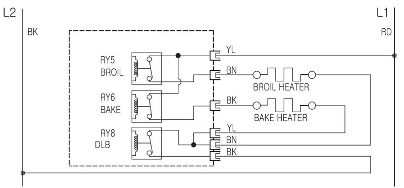
BROIL
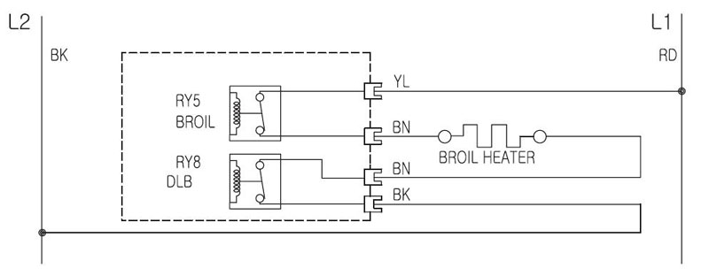
OVEN LIGHT
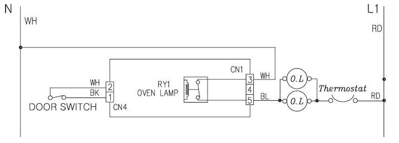
WARMING DRAWER
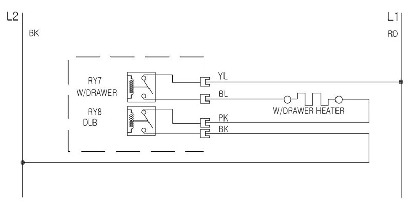
SELF-CLEANING CYCLE
CLOCK DISPLAY ON
CONVECTION BAKE / CONVECTION ROAST
CR (CENTER REAR) ELEMENT (WARMING ZONE)
RR (RIGHT REAR) ELEMENT
LR (LEFT REAR) ELEMENT
LF (LEFT FRONT AND BRIDGE) ELEMENT
RF (Right FRONT) ELEMENT
LOW VOLTAGE CONNECTORS FOR HEATER RELAYS
Relays are Controlled by 12 VDC Ref. to Pin 1 (Orange Wire)
Pin No	Wire Color	Relay 			Relay No 	VDC

1	ORANGE		VDC Ref Line1
2	GREEN		Broil			5		-12
3	BROWN		Bake			6		-12
4	WHITE		Warming Drawer		7		-12
5	BLUE		Convection 		9		-12
6	RED		Double Line Break 2	8		-12
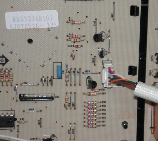

1) Ref Line (Reference Line) is the (+) positive potential of 12 VDC. Main PCB Board switches the (-) negative potential of the 12 VDC to each relay coil. With BK meter lead on Pin 1 Ref line and RD meter lead on Pins 2 thru 6, your meter will show -12 VDC.
2) DLB will have -12VDC along with BAKE, BROIL, WM DRWR, or CONVECTION relay. Measure from Pin 1 (Orange) to any relay coil being tested.
Questions? Comments! Concerns? Report an error?
Let us know!
An e-mail should solve the problem.


